Tartan 37 Workshop
Category 4: MAINTENANCE & SAFETY
(Hull, topsides, lifelines, emergency equipment, teak, exterior/interior finishes, miscellaneous)
These items are submitted by Tartan 37 owners for information only. Your use of a procedure , product or process described in this section is at your discretion, and results are not guaranteed to be to your satisfaction.
Entries in this section (Click on name to view)
STAINLESS STEEL
RAIL
- Sharon & Dave Ragle on Tigger, Hull #2. On our
circumnavigation, we sometimes saw sailboats with stainless steel railing in
place of wiggly wire lifelines. They looked much sturdier. Of course, both
Dave and I know that no railing, no matter how sturdy and secure, is a
substitute for each person taking responsibility for staying on board. We
both feel, as the Pardeys do, that going overboard on a short-handed (couple
sailing) passage most likely means only one will reach shore - so stay on
board.
With that disclaimer, we still wanted those rails! When we reached Durban,
South Africa, we decided that was the place. The exchange rate was
excellent so the labor charges were reasonable, and parts were accessible.
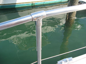
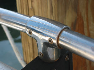 First
we removed the upper wire lifelines. Then a stainless Tee fitting was
placed on the top of the stanchions involved. We were only going
partway forward - enclosing the area most worrisome to me - the side deck
from the cockpit to the shrouds.
The
South African contractor had found 316 stainless for the tubing. To
accommodate the curve of the hull, the tubing was cut the length between
each stanchion. The tubing was then inserted in the Tees and
pop-riveted. However, we did not think that pop rivets were strong
enough in this critical area, so Dave used set screws that went through the
Tee and the tubing.
First
we removed the upper wire lifelines. Then a stainless Tee fitting was
placed on the top of the stanchions involved. We were only going
partway forward - enclosing the area most worrisome to me - the side deck
from the cockpit to the shrouds.
The
South African contractor had found 316 stainless for the tubing. To
accommodate the curve of the hull, the tubing was cut the length between
each stanchion. The tubing was then inserted in the Tees and
pop-riveted. However, we did not think that pop rivets were strong
enough in this critical area, so Dave used set screws that went through the
Tee and the tubing.
 We were so pleased with the set up that when we got back from our
circumnavigation and spent a year in the Houston area giving Tigger a thorough re-fit, we decided to finish the project farther forward.
We were so pleased with the set up that when we got back from our
circumnavigation and spent a year in the Houston area giving Tigger a thorough re-fit, we decided to finish the project farther forward.
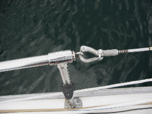
We
planned to leave the wire
on from the pulpit to the most forward stanchion,
so we took the eye that the pelican hook attaches to at an aft stanchion and
brought it to the most forward one. Of course, the bow pulpit has the eye
soldered on.
This
time we had West Marine available for supplies. The Tee fittings are
one-inch "90 degree angle Universal Tees", and the tubing is one-inch
"Polished type 304 Stainless Steel".
RUDDER BEARING REPAIR -
Paul
Pudlinski & Gail Procter, OPPORTUNITY, Hull # 436
I have, what I believe has been the easiest way to replace the rudder
bearing. I was able to get a sketch from Tartan which was a very crude
sketch but was somewhat helpful.
First, look inside the cockpit locker to determine if you have a three or
four bolt rudder bearing. The rudder bearing may be purchased via the Tartan
web site. There is a picture of the rudder bearing so you can visualize how
it needs to be installed.
My boat was on the hard this past winter (Northern Maryland) on a resting
block. I had the yard raise the boat, so two blocks could be put under the
keel; about 16 inches. I also dug a shallow hole below the rudder so the
rudder could be dropped.
The next step was to Remove the steering quadrant from the rudder post so
the rudder may slide down. The steering quadrant is aluminum and the two
halves were corroded together plus the stainless steel bolts were corroded
in place making it impossible to remove them. Three of the four bolts broke
off; so I drilled the three remaining bolts out. A very difficult job. Even
after all the bolts were removed the quadrant halves were corroded together
so I had to split them apart with a sharpened cold chisel and hammer. I
forgot, you must loosen the cables that go to the pedestal. The cable clamps
were also corroded (they were galvanized) and all the bolts broke as I tried
to remove them.
There is a key way in the rudder post and quadrant with a bronze key to keep
the two aligned and from slipping. Under the quadrant are two small bolts
that hold the quadrant together
in addition to the four main bolts; accessed from below.
I completely removed the quadrant so I could drill out the four holes, one
size larger, because the old bolts were drilled out slightly off center. It
isimpossible to drill straight hanging into the locker and drill perfectly
straight and in the center of the bolts. I cleaned the corrosion off,
aligned the two quadrant halves, using new bolts and drilled out one bolt at
a time always having three bolts to keep alignment as best as possible. I
hope your quadrant is not as corroded as mine was.
Under the quadrant, at the top of the fiberglass post is the bronze bearing
with a packing gland. I loosened the bolts but I don't believe it needs to
be loose to remove to rudder post because of the years of wear. There were
reasons for me to remove the packing gland.
The next step is to drop the rudder which is also a project. The rudder post
rest on a thrust bearing (plastic disc) which is on top of the rudder
bearing assembly. The rudder bearing assembly is made up of a thick
stainless steel plate with a pin welded to the top and three of four bolts
through the plate and welded. The pin has the nylon bearing over it and
resides
inside the rudder post.
The rudder will not drop down because the rudder bearing is trapped inside
the skeg. The skeg is bolted and faired to the hull of the boat. I cut a
"window" in the side of the skeg, which is easier than removing the skeg and
I believe it is faster to repair than removing the whole skeg. The window
cut into the side of the skeg was from the front of the skeg to the back on
one side only. The top of the window was located just below the bottom of
the bearing assembly extending down about six or eight inches.
Now you are ready to drop the rudder. Put some blocks under the rudder so it
will drop down leaving about two inches between the blocks and rudder.
Remove the nuts of the bearing assembly from inside the boat (inside the
cockpit locker). I had to hit the bolts with a hammer to get it to slide
down. Now outside the boat, with the rudder supported on blocks, you will
swing the bearing assembly sideways out of the skeg and clear of the skeg so
the rudder may drop out. Remove the blocks and the rudder will drop all the
way out.
Now with the rudder out: Grind or power sand the area just below the
slot where the bearing is captive in the rudder, about one inch below the
bearing assembly. You will notice there is
a line between a one inch thick block and the rest of the skeg. This block
is a different color (mine was pink like Bondo car repair compound) and the
white fiberglass. The block needs to be cut off so the captive bearing
assembly can be removed. Cut the block off in one piece and save it. I have
a small saw so I cut a horizontal cut around the block, cutting only into
the block, not the fiberglass, and not into the back or trailing edge of the
rudder. The bearing
will fall out.
Now install the new bearing. Epoxy the the block in place. I mixed some
colloidal silica with epoxy so I could use a paste to fill in gaps as I
positioned the block. After the epoxy is cured I faired the rudder.
The upper bronze bearing was in good condition so I let it be. There was
evidence of a grease fitting at the top of the rudder post housing at the
top rudder bearing but it was rusted off. I drilled out the old grease
fitting, tapped the hole and installed a new grease fitting. I don't believe
it was ever greased. Tartan told me some boats had grease fittings and some
had none. Also the packing looked to be in good shape so I let it go and
just tightened it.
I slid the rudder under the boat and, with a 2x4 lever, lifted the rudder in
place.
I greased the top bearing and reassembled everything. I replaced the
steering quadrant cable clamps with stainless steel clamps.
To repair the window I ground the edge around the cut to create a bevel in
the loose piece and the skeg. I covered the loose piece with two layers of
Saran Wrap so epoxy wouldn't stick to it. I held the window piece in place
with tape and clamps. I then cut fiberglass in two inch strips and fixed the
strips inside the skeg at the joint of the window cut overlapping the inside
of the
skeg one inch and the window piece one inch, all inside the skeg. I used
about four layers of fiberglass. After the epoxy is cured I removed the
window piece, removed the Saran Wrap, and epoxied the window in place. The
one inch strips helped holding the window piece in place. After the epoxy
was cured I cut strips to infill the bevel at the window/skeg joint. The
first strip narrow, the next strip wider and so on until the bevel is filled
with fiberglass and epoxy. After
the epoxy was cured I faired the skeg; Bottom paint and it was ready to go.
Now the the wheel turns smoothly and with less effort.
I hope you find this useful and if you have any questions please do not
hesitate to ask.
Paul Pudlinski
"Opportunity", T37C, Hull 436